Connected Robot Cell.
Simulation state, made visible.
- ROLE
- Workflow direction & simulation validation
- TOOLS
- Isaac Sim · Python · MQTT · Mosquitto
- DISCIPLINES
- Connected simulation · Telemetry · System integration
- YEAR
- 2026
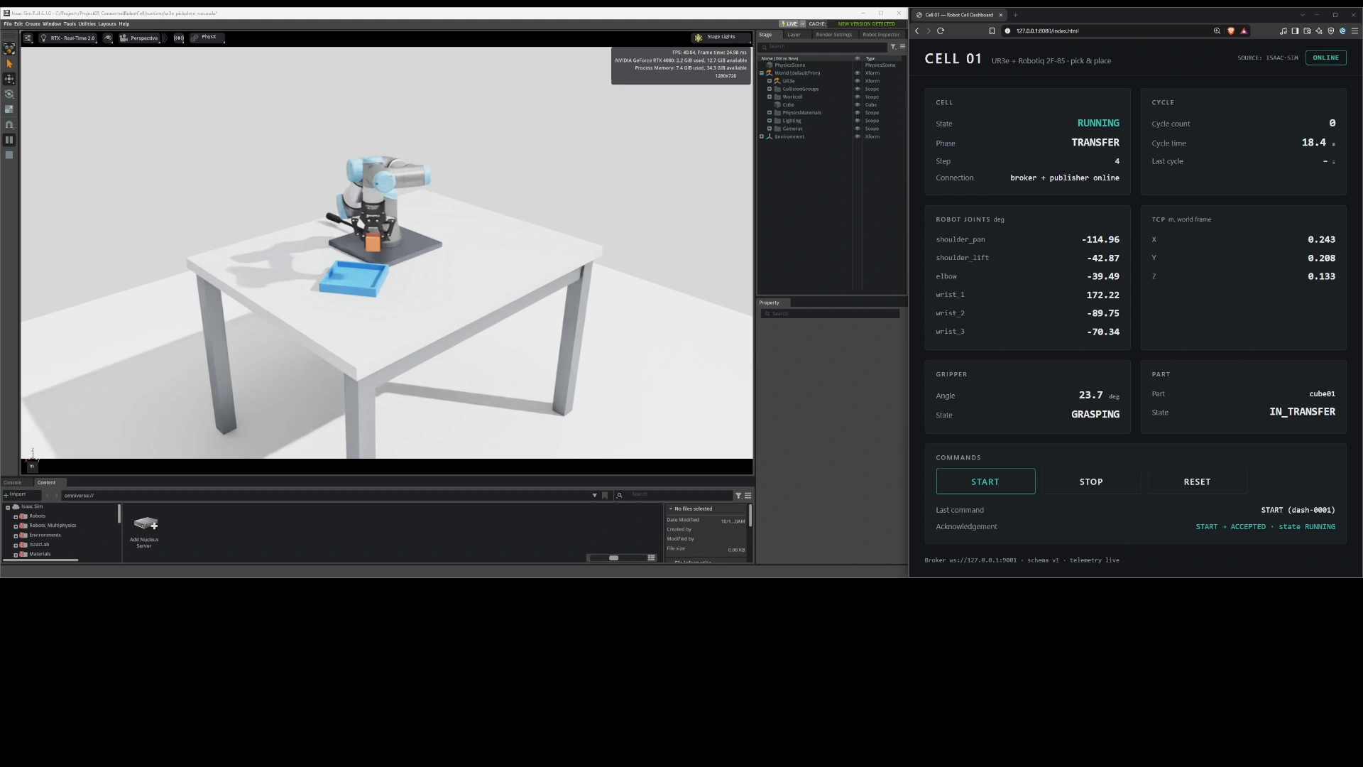
Demonstration description
The desktop recording shows the Isaac Sim UR3e and Robotiq cell beside its browser dashboard. The robot picks up a cube, carries it to a tray and returns home while the dashboard displays cell state, task phase, joints, TCP, gripper and part state. Dashboard controls and acknowledgement messages remain visible. The video starts muted; audio can be enabled through its controls.
A robot task.
A connected system view.
Expose the state of an Isaac Sim pick-and-place cell outside the simulator. A local MQTT connection links the robot task to a browser dashboard, making motion, phase changes and cycle completion visible through structured telemetry.
The cell uses the UR3e with an integrated official Robotiq 2F-85. The connected-cell concept is demonstrated entirely in simulation: the supplied evidence does not connect it to a physical robot or production workcell.
One broker. Two protocol links.
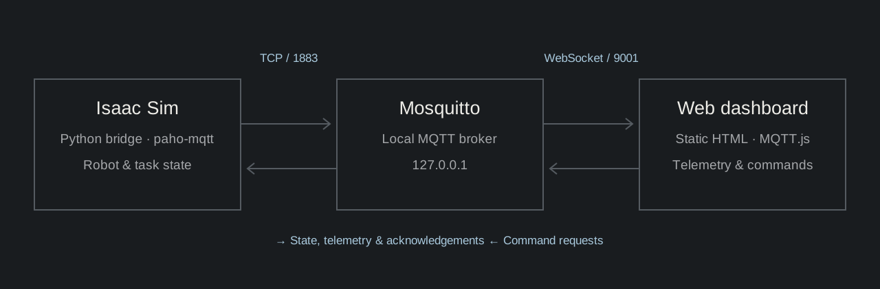
The documented architecture connects a Python paho-mqtt bridge to a local Mosquitto broker over TCP port 1883. A static HTML dashboard uses MQTT.js over WebSocket port 9001.
State and telemetry are separated from command requests and acknowledgements under the cell01/ topic root. Transport checks verified TCP round trips with command-line tools and Isaac Python, plus the WebSocket upgrade handshake.
The architecture record includes verified Mosquitto 2.1.2 and paho-mqtt 2.1.0 setup. Its later pinned-schema note supersedes the earlier draft payload examples.
Motion has context.
The dashboard carries it.
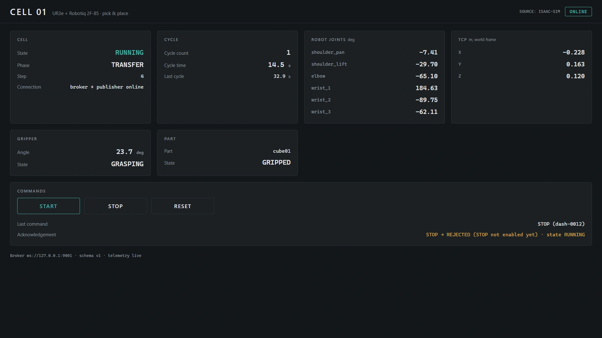
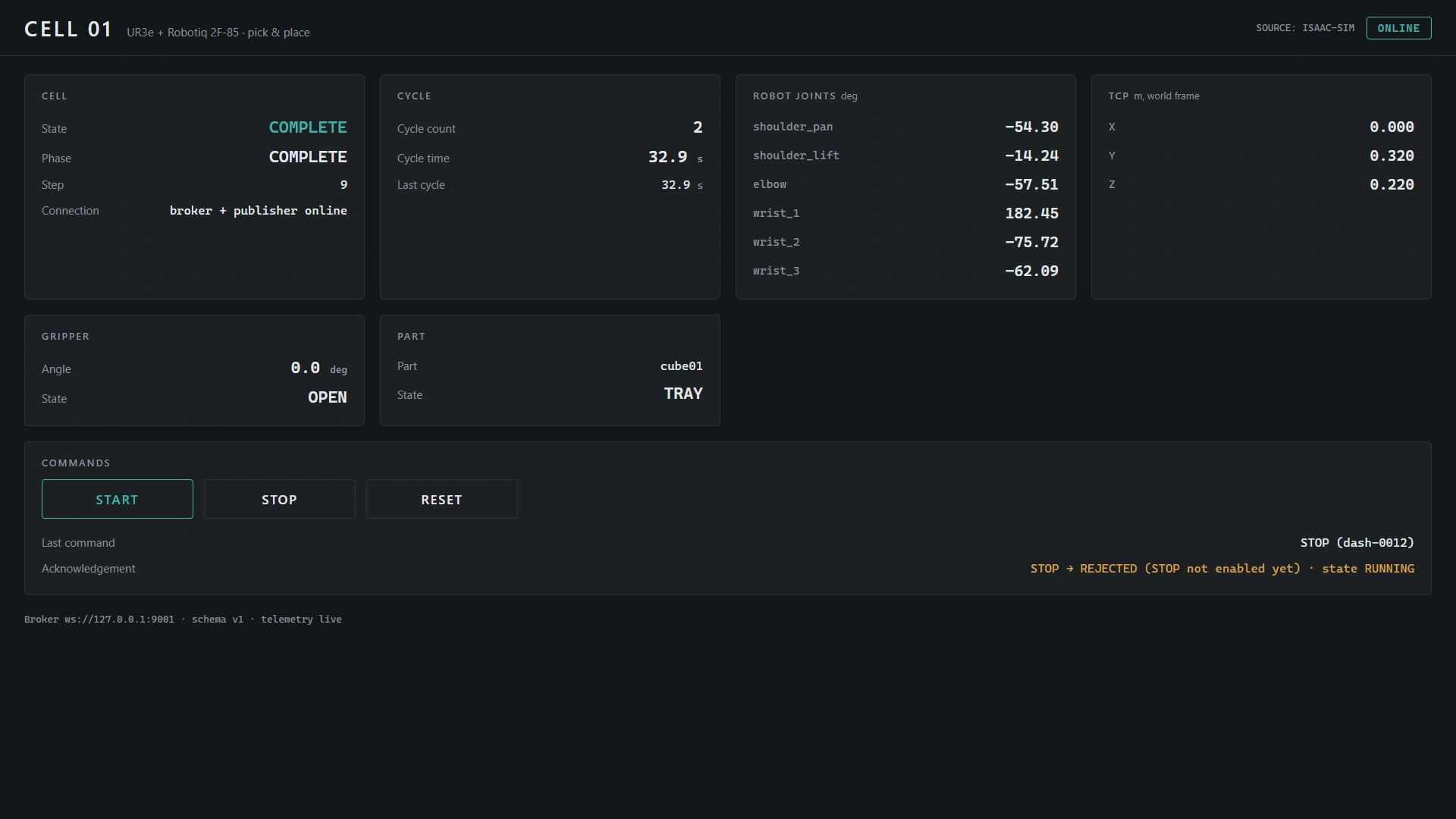
The runtime captures identify the publisher as ISAAC-SIM and show task progress alongside robot state.
Cell & task
Cell state, phase and step describe where the task is in its sequence. Cycle count, elapsed cycle time and last-cycle time provide a separate view of completed work.
Robot, gripper & part
Six joint angles are shown in degrees. TCP coordinates use metres in the world frame. Gripper angle and state appear alongside the cube’s SOURCE, GRIPPED or TRAY state.
Connection & command feedback
The dashboard reports broker and publisher connection state. Its command panel displays the latest request id, accepted or rejected result, and the associated cell state.
A button press
needs an answer.
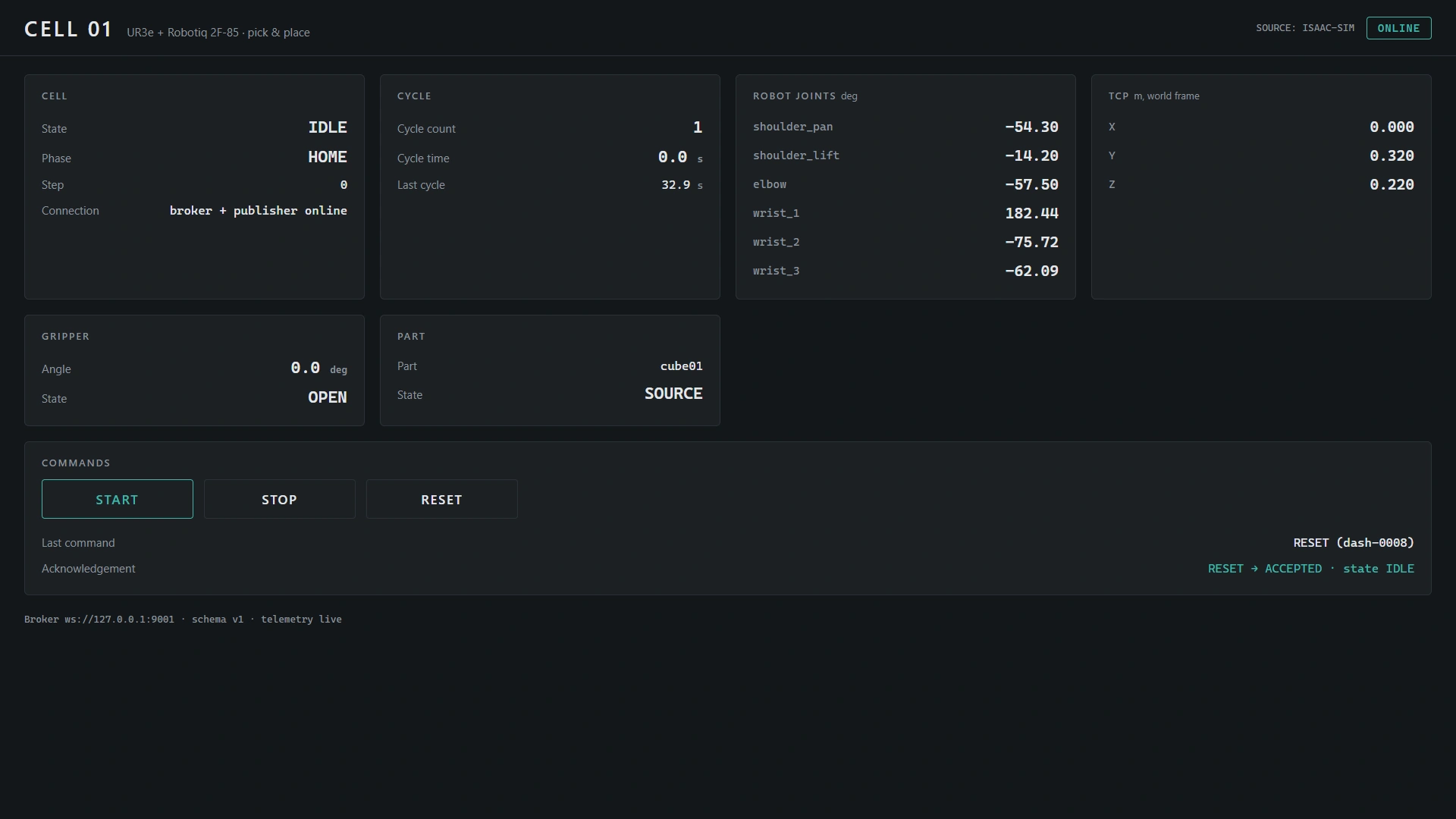
The demonstration exposes START, STOP and RESET controls. Their recorded outcomes define what can be claimed.
| Request | Acknowledgement | Observed state |
|---|---|---|
| START | Accepted | RUNNING; task advances |
| STOP | Rejected: “not enabled yet” | RUNNING; no pause demonstrated |
| RESET | Accepted in later reset capture | IDLE / HOME; gripper OPEN; cube SOURCE |
The accepted-reset capture does not establish the internal reset mechanism. No timeline reload or stage-replacement behaviour is inferred.
05 / RESET & REPEAT
Return to idle.
Run the task again.
The later capture sequence records completion, an accepted reset, then transfer and completion in the second cycle.
Simulation state becomes
system evidence.
The recorded demonstration places the robot cell and connected dashboard side by side. The captures document live simulation telemetry, accepted START and RESET requests, and two completed cycles.
This is a local connected-simulation demonstrator. The supplied material does not establish real-hardware synchronisation, measured messaging latency, reliability under network faults or implemented STOP behaviour.
- Project direction
- Marko Bokan — workflow definition, technical judgement, QA and acceptance.
- Robot foundation
- UR3e simulation workflow with the integrated official third-party Robotiq 2F-85 asset.
- Transport
- Mosquitto, Eclipse Paho MQTT and MQTT.js, as documented in the supplied architecture record.
- Evidence
- Architecture Plan with verified transport and pinned-schema notes; ISAAC-SIM dashboard captures; original 11 October 2026 MKV demonstration, presented here as an MP4 derivative.